- 您现在的位置:买卖IC网 > Sheet目录320 > DK-DEV-5SGXEA7N (Altera)KIT DEV STRATIX V FPGA 5SGXEA7
8-18
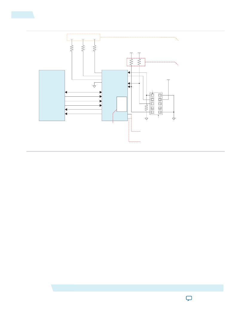
Programming EPCS Using the Active Serial Interface
Figure 8-9: Connection Setup for Programming the EPCQ Using the JTAG Interface
V CCPGM V CCPGM
V CCPGM
Connect the pull-up resistors
to V CCPGM at a 3.0-V power
SV51010
2014.01.10
10 kΩ
10 kΩ
10 kΩ
V CCPD V CCPD
supply.
The resistor value can vary
EPCQ Device
FPGA Device
from 1 k Ω to 10 kΩ. Perform
GND
nSTATUS
CONF_DONE
nCONFIG
nCE
TCK
TDO
TMS
TDI
Pin 1
V CCPD
signal integrity analysis to
select the resistor value for
your setup.
DATA0
DATA1
AS_DATA0/ASDO
AS_DATA1
DATA2
AS_DATA2
Serial
DATA3
DCLK
nCS
AS_DATA3
DCLK
nCSO
Flash
Loader
MSEL[4..0]
1 kΩ
CLKUSR
Instantiate SFL in your
design to form a bridge
between the EPCQ and
the 10-pin header.
Download Cable
GND 10-Pin Male Header GND
(JTAG Mode) (Top View)
For more information, refer to the
MSEL pin settings.
Use the CLKUSR pin to supply the external
clock source to drive DCLK during configuration.
Programming EPCS Using the Active Serial Interface
To program an EPCS device using the AS interface, connect the device as shown in the following figure.
Altera Corporation
Configuration, Design Security, and Remote System Upgrades in Stratix V Devices
Send Feedback
发布紧急采购,3分钟左右您将得到回复。
相关PDF资料
DK-DSP-2S180N
DSP PRO KIT W/SII EP2S180N
DK-DSP-3C120N
KIT DEV DSP CYCLONE III EDITION
DK-K7-CONN-CES-G
KINTEX-7 FPGA CONNECTIVITY KIT
DK-K7-EMBD-CES-G-J
KINTEX-7 FPGA EMBEDDED KIT JAPAN
DK-MAXII-1270N
KIT DEV MAXII W/EPM 1270N
DK-N2EVAL-3C25N
KIT DEV NIOS II CYCLONE III ED.
DK-NIOS-2C35N
NIOS II KIT W/CYCLONE II EP2C35N
DK-NIOS-2S60N
NIOS II KIT W/STRATIX II EP2S60N
相关代理商/技术参数
DK-DSP-2C70N
功能描述:DSP KIT W/CYCLONE II EPS2C70N RoHS:是 类别:编程器,开发系统 >> 通用嵌入式开发板和套件(MCU、DSP、FPGA、CPLD等) 系列:Cyclone® II 产品培训模块:Blackfin® Processor Core Architecture Overview
Blackfin® Device Drivers
Blackfin® Optimizations for Performance and Power Consumption
Blackfin® System Services 特色产品:Blackfin? BF50x Series Processors 标准包装:1 系列:Blackfin® 类型:DSP 适用于相关产品:ADSP-BF548 所含物品:板,软件,4x4 键盘,光学拨轮,QVGA 触摸屏 LCD 和 40G 硬盘 配用:ADZS-BFBLUET-EZEXT-ND - EZ-EXTENDER DAUGHTERBOARDADZS-BFLLCD-EZEXT-ND - BOARD EXT LANDSCAP LCD INTERFACE 相关产品:ADSP-BF542BBCZ-4A-ND - IC DSP 16BIT 400MHZ 400CSBGAADSP-BF544MBBCZ-5M-ND - IC DSP 16BIT 533MHZ MDDR 400CBGAADSP-BF542MBBCZ-5M-ND - IC DSP 16BIT 533MHZ MDDR 400CBGAADSP-BF542KBCZ-6A-ND - IC DSP 16BIT 600MHZ 400CSBGAADSP-BF547MBBCZ-5M-ND - IC DSP 16BIT 533MHZ MDDR 400CBGAADSP-BF548BBCZ-5A-ND - IC DSP 16BIT 533MHZ 400CSBGAADSP-BF547BBCZ-5A-ND - IC DSP 16BIT 533MHZ 400CSBGAADSP-BF544BBCZ-5A-ND - IC DSP 16BIT 533MHZ 400CSBGAADSP-BF542BBCZ-5A-ND - IC DSP 16BIT 533MHZ 400CSBGA
DK-DSP-2S180N
功能描述:DSP PRO KIT W/SII EP2S180N RoHS:是 类别:编程器,开发系统 >> 通用嵌入式开发板和套件(MCU、DSP、FPGA、CPLD等) 系列:Stratix® II 产品培训模块:Blackfin® Processor Core Architecture Overview
Blackfin® Device Drivers
Blackfin® Optimizations for Performance and Power Consumption
Blackfin® System Services 特色产品:Blackfin? BF50x Series Processors 标准包装:1 系列:Blackfin® 类型:DSP 适用于相关产品:ADSP-BF548 所含物品:板,软件,4x4 键盘,光学拨轮,QVGA 触摸屏 LCD 和 40G 硬盘 配用:ADZS-BFBLUET-EZEXT-ND - EZ-EXTENDER DAUGHTERBOARDADZS-BFLLCD-EZEXT-ND - BOARD EXT LANDSCAP LCD INTERFACE 相关产品:ADSP-BF542BBCZ-4A-ND - IC DSP 16BIT 400MHZ 400CSBGAADSP-BF544MBBCZ-5M-ND - IC DSP 16BIT 533MHZ MDDR 400CBGAADSP-BF542MBBCZ-5M-ND - IC DSP 16BIT 533MHZ MDDR 400CBGAADSP-BF542KBCZ-6A-ND - IC DSP 16BIT 600MHZ 400CSBGAADSP-BF547MBBCZ-5M-ND - IC DSP 16BIT 533MHZ MDDR 400CBGAADSP-BF548BBCZ-5A-ND - IC DSP 16BIT 533MHZ 400CSBGAADSP-BF547BBCZ-5A-ND - IC DSP 16BIT 533MHZ 400CSBGAADSP-BF544BBCZ-5A-ND - IC DSP 16BIT 533MHZ 400CSBGAADSP-BF542BBCZ-5A-ND - IC DSP 16BIT 533MHZ 400CSBGA
DK-DSP-2S60N
功能描述:DSP KIT W/STRATIX II EP2S60N RoHS:是 类别:编程器,开发系统 >> 通用嵌入式开发板和套件(MCU、DSP、FPGA、CPLD等) 系列:Stratix® II 产品培训模块:Blackfin® Processor Core Architecture Overview
Blackfin® Device Drivers
Blackfin® Optimizations for Performance and Power Consumption
Blackfin® System Services 特色产品:Blackfin? BF50x Series Processors 标准包装:1 系列:Blackfin® 类型:DSP 适用于相关产品:ADSP-BF548 所含物品:板,软件,4x4 键盘,光学拨轮,QVGA 触摸屏 LCD 和 40G 硬盘 配用:ADZS-BFBLUET-EZEXT-ND - EZ-EXTENDER DAUGHTERBOARDADZS-BFLLCD-EZEXT-ND - BOARD EXT LANDSCAP LCD INTERFACE 相关产品:ADSP-BF542BBCZ-4A-ND - IC DSP 16BIT 400MHZ 400CSBGAADSP-BF544MBBCZ-5M-ND - IC DSP 16BIT 533MHZ MDDR 400CBGAADSP-BF542MBBCZ-5M-ND - IC DSP 16BIT 533MHZ MDDR 400CBGAADSP-BF542KBCZ-6A-ND - IC DSP 16BIT 600MHZ 400CSBGAADSP-BF547MBBCZ-5M-ND - IC DSP 16BIT 533MHZ MDDR 400CBGAADSP-BF548BBCZ-5A-ND - IC DSP 16BIT 533MHZ 400CSBGAADSP-BF547BBCZ-5A-ND - IC DSP 16BIT 533MHZ 400CSBGAADSP-BF544BBCZ-5A-ND - IC DSP 16BIT 533MHZ 400CSBGAADSP-BF542BBCZ-5A-ND - IC DSP 16BIT 533MHZ 400CSBGA
DK-DSP-3C120N
功能描述:可编程逻辑 IC 开发工具 FPGA Development Kit For EP3C120F780
RoHS:否 制造商:Altera Corporation 产品:Development Kits 类型:FPGA 工具用于评估:5CEFA7F3 接口类型: 工作电源电压:
DK-DSP-3SL150N
功能描述:可编程逻辑 IC 开发工具 FPGA Development Kit For EP3SL150F1152
RoHS:否 制造商:Altera Corporation 产品:Development Kits 类型:FPGA 工具用于评估:5CEFA7F3 接口类型: 工作电源电压:
DK-DTK-120HW
制造商:FLORIDA MISC. 功能描述:
DKE10
制造商:MEANWELL 制造商全称:Mean Well Enterprises Co., Ltd. 功能描述:10W DC-DC Regulated Dual Output Converter
DKE10A-05
功能描述:DC/DC转换器 9-18Vin +/-5Vout 100-1000mA, 10W RoHS:否 制造商:Murata 产品: 输出功率: 输入电压范围:3.6 V to 5.5 V 输入电压(标称): 输出端数量:1 输出电压(通道 1):3.3 V 输出电流(通道 1):600 mA 输出电压(通道 2): 输出电流(通道 2): 安装风格:SMD/SMT 封装 / 箱体尺寸:
